In my original head the exhaust guide that I removed was 0.502" in diameter, the inlet 0.500". Half inch appears to be the std size so the exhaust must have been changed at some stage. Both my new guides were 0.502 which is OK for the exhaust but presents a problem for the inlet. The general wisdom is that for brass guides in an alloy head, then the guide receiving holes in the head should be 1.5-2 thou smaller than the guides to achieve an interference fit. The exhaust guide is therefore fine but its likely that the hole for the inlet guide is too small for a 502 guide in this position. I should either get another (smaller) guide or enlarge the hole.
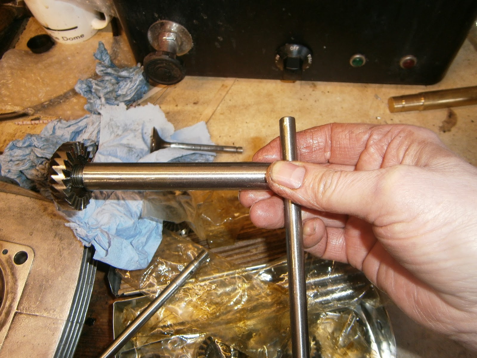
The installation tool is shown here, new valves are effectively both exhausts. I boiled the head again - I have an old dental sterliser that is just big enough, and put the guide in the freezer to maximise size compatibility and then installed the exhaust guide.
 |
| Installation tool consists of threaded shaft with conical head, 2 valve adapters and a shaft nut. There is also a hex wrench to hold the conical head as the nut is tightened. The brass object here is the new guide. |
 |
| Conical head seated on the valve seat internally. Note hex key hole in the head to hold it whilst the draw nut is tightened. |
 |
| The tool is assembled as shown; the conical head fits into the valve seat in the head with the thread projecting backwards. The guide is slipped over this and aligned in the hole in the head. An appropriate spacer is applied behind the new guide- one for flat ended guides and one for tapered. The tapered end of a tapered guide should slip inside the tapered counterbore of the adapter- in my case it didn't so I used the plain adapter. The final step is to tighten the nut down onto the shaft, holding the conical headpiece on the inside with the Allen key. As the nut is tightened the valve guide is drawn into the hole. Its properly seated when the flange abuts the head. |
 |
| New guide in position. Note that in reality I had infilled the bolt holes already for thread repair (see below) |
Fitting the inlet guide however, presented a problem. It is probable that it would fit simply as above, but the hole will be at least 2 thou too small and so carries the risk of cracking the head. I ordered a 0.5 inch reamer to enlarge the head hole to 500 thou. This should then give the required squeeze on a 0.502 guide if the reamer is sized that accurately. The reamer came and was surprisingly well sized- its shaft measured 500 thou dead on. I reamed the valve guide holes by hand allowing the reamer to pass right through once using plenty of cutting oil, rather than withdrawing it as they can cut again on the way out. This didn't remove much material but still resulted in a snug fit for the guides which were easily installed using the tool as above. I ordered two new guides in order to restore both heads.
 |
| New guides installed. |

I ordered a cheap set of valve seat recutters. As so many tools these days, they came from India- but hey I figure that they still manufacture the Royal Enfield and of course the Morris Oxford so they should understand imperial! This set has a wealth of different sized and angled cutters plus the handles and pilots so I reckoned that at about 20 quid it was really good value. Downside- it wont work on hardened seats used for unleaded- this would need carbide cutters which are dearer.
 |
| I selected a cutter that matches the valve and a 45 degree angle |
 |
| The cutter is screwed onto the handle |
 |
| The set comes with a set of imperial plots and one of these fits the BSA valves perfectly. The pilot screws into the cutter handle to hold the cutter parallel to the guide. It has to be done up tight as it mustn't wobble! |
 |
| I used cutting oil on the cutter and grease on the pilot shaft, inserted it into the guide and rotated it to cut the seat again. |
 |
| The front seat has been recut already- the one at the back is shown here before recutting... juyst as an aside I did also clean up the plug hole threads with a chaser- they have come up very nicely too. |
 |
| ...and here after the recut. This second hand head was significantly marked inside which I think comes from decades of using inappropriate decarbonising tools. Luckily they don't affect any of the sealing areas-either valves or barrel. |
The fitting process causes the guides to pinch up and distort a little. These days its recommended to ream the guides when fitted to ensure that the valves operate smoothly. The exhaust guide usually requires a larger clearance as it runs hotter; about 2 thou clearance guide-to-stem is OK and the inlet needs about 1 thou. The stems of these valves are made to different diameters and differ by 1 thou (exhaust is smaller)so that the same reamer can be used for both guides. Accordingly I also ordered a 5/16 reamer to ensure that the guides are parallel after fitting and to arrange the correct clearance; At 0.3125", this reamer is 0.0005 larger than the size required but its far cheaper than buying the absolutely correct 0.312 inch reamer.
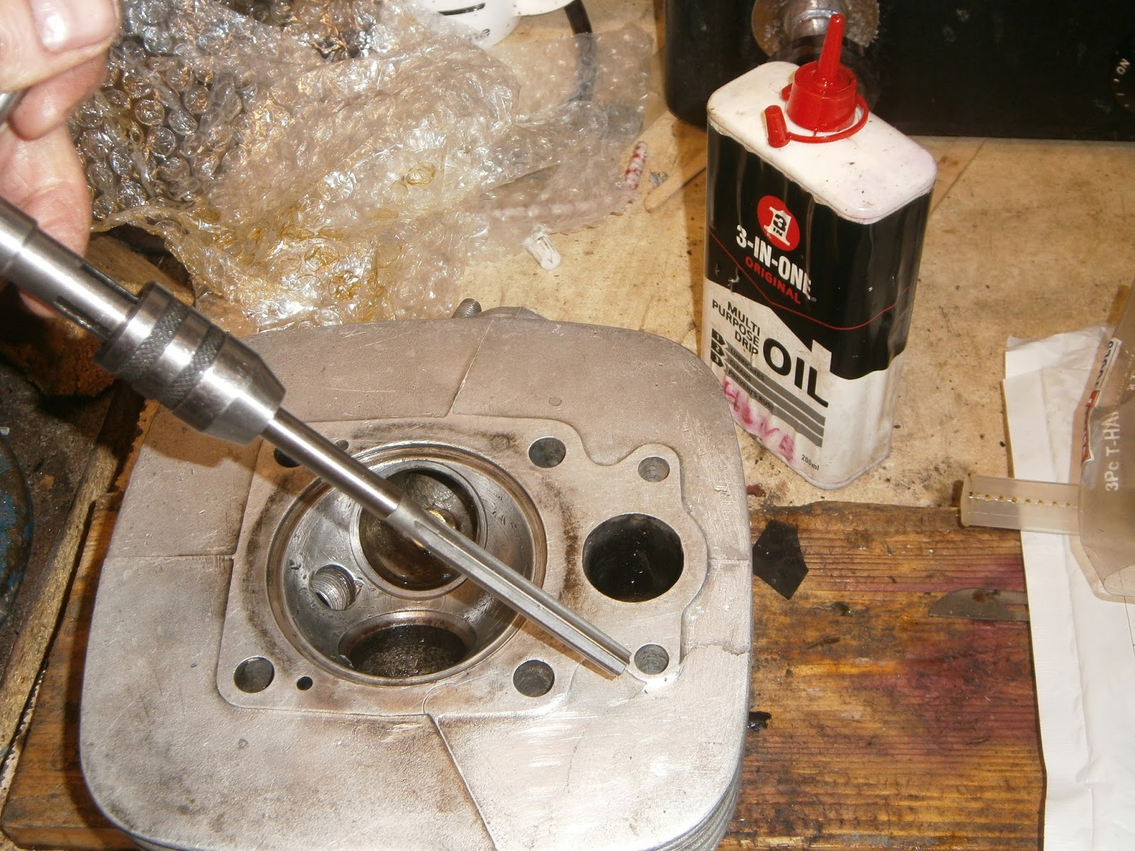 |
| 5/16 reamer- use cutting oil- note I have cutting oil in the 3-in-one can, although I think that would work too. |
I ground in the valves, cleaned and refitted them with their springs- note re compressor arm position as above- it must not foul the rocker box flange.
A word about cleaning the head...
Throughout this the heads were fairly mucky- the second hand head was definitely the worst
 |
| Heavily carbonised second head |

 |
| Inside exhaust housing cleans up nicely |
 |
| As does the head and ports, note spigot recess also cleaned out. |
 |
| Last stage was to clean up the gasket face using a Ro-Loc bristle brush (yellow grade) in a hand drill |
 |
| Rocker mounting flange also cleaned up. |
Thread Repair
Chronologically I was repairing the threads at the same time as fitting the guides- and had completed this before I fitted the valves, but it seems to make more sense to explain the process of sorting out valves and guides completely before I addressed the repair of the threads. Apologies if this causes confusion...
A note about threads.
BSA (and Triumph for that matter) have used a multiplicity of thread sizes over the years and although some understand it- I certainly don't. What I have gleaned is this: Studs in particular tend to have one end in alloy and the other in a steel nut. The threads used on these ends are often different (at least in early bikes) partly because of the different strengths of these materials and the fact that studs aren't removed as often as nuts, but perhaps most importantly, that they grip in different ways: Nuts tighten through torque twisting onto the threads (which pulls the nut down and the stud up). Studs are fitted into the head at a much lower torque and grip largely through the pulling action of the nuts rather than a turning force. Alloy in particular can strip easily if you overtighten (twist) a stud or bolt. For these reasons BSA tended to use a coarser pitch in alloy than in steel. In this case I am particularly interested in the 1/4 inch studs fastening the rocker box onto the head.
Pre-unit bikes used a Whitworth thread in alloy and a cycle thread BSC (aka CEI) into the steel nut. For the 1/4 studs at least the ww was 20 tpi and the BSC 26 tpi. With unit construction the WW was superceded by BSF threads. This is also 26 tpi but the angle of the thread peaks between the grooves is different, presumably this improves resilience in alloy (maybe ?). After 1968 BSA moved to UNC threads for both ends of these studs (so did it ever matter?). For my bike this means that I should have UNC threads... but I don't! I seem to have BSF on the lower end of the stud and BSC on the top, both 26 tpi which I suppose is to be expected for a bike made after 68, but according to a design that's much older. Since these threads are of equal pitch they will mate and a BSC stud will screw into a BSF hole and vice versa. However the thread cut is likely to be distorted if you do this. Given that they must have been loosened several times over the 50-year life of the bike (and some have even been put back the wrong way round) it is clear that the differences between these ends are now hard to detect and most of the threaded holes in the head are loosened- some stripped out. However if I am re-threading the head and fitting any new studs then I'd like to get it right.
The first point is what way up should the studs be? Mine have been mixed up. Examining the studs showed that the threaded lengths are different at each end: The shorter end I think is intended to go into the head since the alloy flange to which the rocker will fit is not very deep, and longer threads would screw right through. Consequently this end should be BSF. For some of the studs this thread length difference isn't so clear because they screw more deeply into the head than those on the flange.
Thread Repair.
Threads with minor damage can be restored by chasing with a tap or die. If you are unsure which thread is which then the recommendation seems to be:
- For Studs; use a BSC die first and check fit. If its tight chase it through with a BSF die.
- For Holes; Use a BSF tap first and check, if its still tight chase it through with a BSC tap.
Using the threading tools in this way cuts the smallest amount of metal in the first pass in each case, after all you can always take more off but can't put any back!
Threads with major damage are more tricky and there are three ways of fixing them:
1. Re-thread: 1/4 inch is actually very close to M6, and M6 studs are easily bought. If you aren't worried about originality then this might work but I suspect stripped threads will already be enlarged past this approach. If this doesn't work then you can drill out and re-thread the hole at a bigger size. M7 could be used at a pinch and is common for studs on many moped cylinders (Zundapp), some may be about the right length? M8 is likely to be way too big. Even M7 though does mean that the stud will be larger, which may mean that either the component into which it fits may need modification- or a one-off special stud has to be made with different diameters at each end. This sort of approach is the only one I have tried to date.
2. Clean the hole, fill it with aluminium weld, re-drill and tap to original size. Sadly, TIG welding is quite an art, and since I have neither equipment nor experience this isn't practical for me. However, aluminium repair rods are available, and if these work then it would be a really useful process to acquire. The repair rods are self fluxing and can be fitted with a brazing torch. They come in 2 grades with melting points 300 or 400 degrees centigrade. However, as aluminium doesnt melt until around 660deg, the rods arent likely to merge with the originsal material. The higher melting point rod is recommended for stressed areas like threads.
3. Drill out the hole, tap and re-thread to the original size using a helical insert such as helicoil or V-coil. These are available in a variety of sizes imperial and metric, but they are expensive. Metric versions can be cheaper and so going metric might be a good idea cost-wise if you can get M6 studs of appropriate lengths.
I would like to stay original so option "1" isn't a solution this time. I do have equipment to take option "2"; it is cheaper than a coil insert and doesn't enlarge the hole. Lastly, Even if its a total failure then option "3" would still be available to enlarge the hole and use a coil. Accordingly I'm going to try the aluminium repair rod first.
I decided to try to repair the original head using the aluminum repair rod approach, and the second head using helicoils.
Using Aluminium repair rods.
I obtained both types of rod from eBay- AL300 and AL400. To prepare the head I washed it extensively in degreasant and then boiled the head to lift as much contamination off the metal as possible. This also puts a lot of heat into the head and should help to reach the repair temperature.
The rule for using this material is that it will melt into the existing aluminum but only if the existing metal is hot enough. The repair rod must melt on contact with the hot metal not the flame!
Success was mixed: Firstly, I couldn't get the head hot enough to melt the AL400. This might be because I was using a butane cartridge in the torch, I believe a butane/propane mix will give a hotter flame. The other problem is that aluminium simply conducts the heat away from the flame point very efficiently, after all this is exactly what the head is designed to do! Perhaps I should be more patient?
 |
| Thread repair head 1- using Al300/Al400 rods |
I used a piece of steel wedged below the flange to block off the hole.
 |
| Infill with repair rod |
 |
| File smooth and repair second hole |
 wa wa |
| Rocker box in position, I then marked the position of the hole needed by passing a closefitting drill through the hole using the pillar drill and drilling just enough to mark the position needed.. |
 |
| I tapped the hole using a 1/4 BSF tap |
 |
| Result wasn't at all bad! It certainly took the studs well. |
*- I did try! No luck!!
The TIG experience!
I sent my original head (head 1) off to a professional welder to build up the area around the missing flange with weld. The head was returned with a great big irregular lump of aluminium welded on.


This was at least easily machined so with a combination of hand filing and disc cutting I was able to restore a reasonably good profile, flush with the gasket face of the rocker flange.

I have found in this job that getting the threads drilled cleanly and accurately is key to getting the rocker box to sit well on the head- some of the holes I had drilled earlier weren't exactly right and the box was stiff to fit. I recommend therefore that whenever possible you actually drill the holes with the box in situ rather than just marking them and then removing it,. To my surprise the 1/4 inch tapping drill- and even the tap fitted nicely trough the rocker box and allowed me to drill an accurately positioned hole and tap it vertically.
 |
| Tapping drill and 1/4" tap fitted through the rocker box- drill in situ and start the tap as well. |
 |
| New hole drilled and tapped. |
Having sorted this hole I was then able to ream the guides, re-cut the valve seats and decarbonise the chamber and ports completing the renovation of this head.
Helicoil (V-coil repair)
I decided to try a helicoil repair using the second head.
 |
| V-coil kit, drill, tap, insertion and tang breaking tool plus several inserts at 1/4 BSF |
 |
| Step 1- drill out the holes taking care to be on target and vertical- clamping the head firmly helps accuracy |

 |
| Guide coil with a finger as it starts to screw in. |
Thread in the helicoil insert to just below surface of the alloy using the insertion tool- pass it through the helix and engage the tang at the bottom. Position the coil above the threaded hole using your fingers and start it carefully into the thread. Screw in evenly and gently, do not reverse motion or the tang will probably break off.
Break off the tang using the tool.- its quite straightforward, just place the tool on the tang and give a sharp knock downwards. As these are through holes the tang simply drops out.
 |
| Tang break off tool |
I repaired two holes like this before removing both valve guides as above. Both were a great success! Helicoil is a really neat solution to this problem, it costs more but its quick, simple and effective. I test fitted the studs which all screwed in nicely although I think all will need Loctite threadseal.Once the threads were fixed I was able to complete the renovation of head 2 as described above. I now have both finished and need to sort out which one to use.
No comments:
Post a Comment
Usual disclaimers! I' m not a mechanic and these blogs are really just documenting my progress. They are neither a recommendation nor an instruction manual. Just my notes for what I did and how Id do it next time. Im always happy to receive suggestions and corrections to any of the processes described here- hey its a learning process for me too! Feel free to contribute...