Search for tasks. Type in a few keywords.

Wednesday 27 July 2016

Fleetstar Seat Recover

I have recovered and refoamed several bike seats by now. This one was by far the least satisfactory. Not only are these humped seats much trickier than the usual flat form; I don't actually think that this seat is the correct one for the bike and although I had assumed (as had the PO) that it was the expected BSA humped type, I  now think that it isn't. I've seen lots of pictures of fleetstars with this type of seat, its got a much lower hump and its a little shorter overall. I think that BSA fitted the C15 Sportsman seat to these bikes but havent been able to prove it. Certainly the age and condition of the foam suggests that this is original. The cover however has been replaced. The PO (like me) expected the humped seat and fitted a humped seat cover- which was unsuccessful. Sadly when I sought to replace it I made the same mistake. A humped cover over a sportsman seat just doesnt fit. This meant that I had to make a lot of ad-hoc changes to my foam and the result was less than satisfactory. I think the result is no more than "passable". If you want to follow my learning curve I describe my steps below and I really think this would give a good result if you have the right seat and foam to start with ...  but bottom line: if I were to do this job again I think I would get it done for me!

When I got this bike I was told that the seat cover was split- I had believed that the foam and pan were OK though so it came as a bit of a shock when I removed the seat and found the rear of the bike was covered in nasty crumbling foam dust!
One of the seat pan captive bolts has come adrift with a break in the pan- nothing to reattach it to! The breakdown foam particles were pouring as a dust out of this hole.

Better remove the old split covering! Its held on by bent shark-teeth on the inside, and a chrome trim strip on the outside. The strip is held by captive  head Tee bolts that fit inside the trim's rear groove. These are drilled through the seat pan side and bolted on the inside with a 1/8 WW nut and washer.These were the devil to get out because they were recessed beneath an edge  trim strip applied under the seat cover and visible here as a bulge at the seat edge.

The foam underneath was disgusting! Deteriorated and crumbling- no strength in it at all.

Seat Pan needed de-rusting and welding to patch the hole for the captive bolt and also for the edge where there is a split. Seat trim strips are  shown detached. The edge trim beneath the cover had done no good at all and seemed to have promoted rusting. When I refit I will fit the trim around the edge- over the cover!
Underside of pan. Edge trim which promoted rusting around the edge is still in position in this picture,.


I have welded the pan-fitting two new captive studs. I will treat it to some anti-rust chemicals and stonechip. In the mean-time I am trying to get a new foam and cover. Not cheap but unavoidable. A new seat is around 200 quid and doing it myself should be less than half that.


Seat Pan painted in black hammerite. welded patch visible
I need a new foam and cover- the cover I must get pre-made as sewing a new one is beyond me, however a new foam is £60, and I should be able to improve on this. I ordered a block of 6BLRECON foam- a reconstituted firm foam of size 60x13x26 cms which is a good approximation to the base size. In order to simplify matters I asked the supplier to make the first cut as a simple step (sadly they couldn't cut slopes). I asked for the block to be cut down to 5cms in height for a distance of 51 cms from one end.

I also need some new T bolts to fix the trim strip back on, Mine had three one side and only two the other. As some of the hounds teeth grippers have snapped off as they were bent back into position I will need more bolts to hold the cover firmly. The existing bolts have heads that are 0.35 x 0.56 inches in size and their stems had 1/8ww nuts. I will have to source an approximate equivalent, which turned out to be item  BSF495. from Bresco.com. These have a metric bolt (m4) and the heads are slightly different in size but can be filed down.

I ordered the new seat cover from Ebay and got a very decent cover made by Viper. It came with misleading instructions telling me to fit it using staples (?) and that it didn't require an edging strip- although strangely the unnecessary edge strip was in fact provided?? I have now recovered about a dozen bike saddles and I have yet to find one where fitting with staples would be appropriate (or even possible as classic bike pans are metal) so I have no idea what they are going on about. Sorry for the rant but I am a literal person and I love instructions. It bothers me when they are clearly not suitable for the bike or part supplied. Anyway the trim supplied is a nice piece of smart chrome/plastic edge strip. Its intended to be fitted over the seat cover where it folds over the edge of the pan and this is a more usual arrangement. However, the trim I found  in place was under the cover. I think the latter is probably correct if you are going to refit the bike's original chrome side trim strips as I intend (hence my search for new T bolts above), or possibly just use a black trim for the edge if fitting over . If you don't do this then you would end up with two chrome strips down the seat and I can just bet that they wouldn't turn out to be parallel!


Cutting the foam
I orderd foam block of 26x60x34 cm size and cut down to 5cm height for 51 cms of its length. I asked the company to make this first cut and so I received a step shaped foam which could be further processed. To make these cuts I am using an electric carving knife which worked really well on this firm foam. I intend to apply a covering of softer foam afterwards.


First cut is 3cm back from the factory cut step and made app 45 deg. This meets the base of the step to give the chamfer.


Here the chamfer is marked on the side


I marked the back of the foam for the rear chamfer 9cms down from the top of the step.

I allowed a 1cm top gap between the cuts and joined up the lines to show the rear slope

Finally I marked the underside of the foam to give the base relief. I went for a 12 cm slope but experience shows that 9 would have been a better starting point.

Finally I connected the lines on the side of the block to give the profile I was aiming for.

Carving knife for the cuts, take it slow and let the knife do the slicing. Don't push it through the foam, allow it to sink at its own rate.
First cut

1st two cuts

Finally cut the base relief.


Lay the pan on the foam, note that here the base cut is really about 3 cms too long and should have been 9 cms not 12.

Draw outline of the pan onto the foam

... and trim vertically downwards to shape. I then cut a 45 degree chamfer- with hindsght I would have left this until after the following step which was to apply the 1cm medium foam cover for the seat area....

The product was a pretty fair approximation of the old foam shape. Front needs trimming and the sides aren't quite even yet,  but this was easily fixed. However- see on, this foam was still too small for the cover- possibly the old one had simply contracted and so wasn't really suitable as a template or alternatively its simply the wrong cover for this seat.


However, it was at this stage that the poor fitting was first obvious. The cover was simply too "humped": there was a large void in front of the chamfer. To correct this I fitted the wedge released by cutting the base relief inverted in front of the top section. This just about took up all the spare room and stuck well using spray carpet adhesive- remember to spay both surfaces and wait 5 mins  for the solvent to flash off before applying them to each other.


I could then cut the 1 cm medium foam sheet to shape of the seat body


... and apply it to the seating area

I cut another section and glued it over the back of the seat to smooth the contours. note second chamfer now cut around the edge of the blue foam. I didn't need to chamfer the base layer. This ad-hocery has produced a foam with a much more pronounced hump

Test fitting the cover at the front using one or two hounds teeth just to hold it in position. The cover turned out to be about 4 cms longer than both the pan and the foam! I had to insert another packer at the front to take up this room and then fold the cover back to fix by the hounds teeth at the front of the pan.
 This test fit showed that the rear of the seat still had some slackness, also the rear was stretched over the steel pan side which didn't provide a smooth back section. I cut another piece of thinner foam and glued this to the rear of the seat pan to give a smooth profile by disguising the join between metal and foam and also put an extra pad in at the front to take up some of this excess space. It seems that this seat cover is really too big for the pan and foam; perhaps the seat has been swapped at some stage? Incidentally I would recommend getting a cover without the BSA logo if possible as these are harder to fit  because they show up any misalignment.

Fitting the cover, compress foam by pushing down seat pan and stretch cover onto alternate hounds teeth to take up the shape.
I fitted the seat cover loosely and left it overnight to allow it stretch before I tightened it up the next day. 
No pics for this part but some observations: Stretching a humped seat over the hump tends to lift the cover from the pan in front of the hump so its difficult to make the stretch even. Eventually I was forced to glue that section down to hold it while I stretched the rest.

The edges of the seat could be held loosely in the hounds teeth but to fix them in position I used these Woolies Trim clips

Woolies edging clips. Fit them with the half-moon side inside the saddle.
The clips are hidden by woolies edging strip into which they fit neatly (herringbone plain black). I used this rather than the chrome trim supplied because I want to refit the original chrome side strips and two chrome lines will look odd.
Seat cover in place, Woolies trim covering the edge clips. Still needs cleaning. The cover was simply too big for the pan and whatever I did I couldn't avoid excess material at the front.  Hopefully this will be hidden when the tank is mounted.

Final effect isn't the neatest in the world, although it will clean up a bit after I have refitted the seat mountings. However, its solid and usable; and a lot better than the seat as fitted when I got the bike. It was also achieved at less than 1/3 the price of a replacement seat, I  reckon its better than 1/3 the quality so win-win; but this is clearly a matter of personal opinion and I think this could undoubtedly be improved.
Tank back on but everything still needs a clean.
I fitted the original chrome trim strip using these new M4 Tee bolts from Bresco. They were slightly too wide but were easily filed to fit into the trim from behind. Here you can see the new bolts and the old 2BA items.


I put the strip in position spreading the tee bolts evenly- 5 per side. This is more than were there originally but I think the strip has an important role in retaining the cover- more so since some of the hounds teeth broke off when used again. I marked where the bolts should come  on the saddle cover and drilled the holes through the cover and steel frame underneath. Holes were drilled at 4.5 mm so that the bolts fitted easily through them.
Trim strip positioned on the outside and the bolts were fed through the holes and tightened.- inside view. These new bolts have integral nuts and washers which makes fitting less fiddly to install.


Seat loosely placed on bike. I will take some update photographs when I get the thing back together.


Wednesday 4 May 2016

Jobs I hadn't expected to do again (2)! Tappets revisited.

Adjustment... Method 2
The manual suggests that the tappets should both be adjusted at the same time, i.e. when the piston reaches tdc. and both valves are therefore fully closed. This does give a noisy setting, although it's the sound that I personally am used to.

 However I have been recommended a second method that should give a quieter setup.


  • Set piston at tdc
  • Rotate both adjusters to vertical, with the flats facing one another.
  • Engage gear and turn the motor backward using the wheel until the inlet just tightens up- ie doesnt open but is about to!
  • Adjust exhaust clearance
  • Turn motor forwards until exhaust just tightens up
  • Adjust inlet valve clearance


No real pictures for this- nothing much to show but I took advantage of the need to remove the tank again for cleaning in order to get better access and perform this readjustment. I found it was necessary to turn the motor a surprisingly long way before the relevant tappet tightened up. Maybe that shouldn't be surprising as virtually a whole  piston stroke is required. Of course I cant start it up and tell whether this method has worked until I fit the new fuel taps.

Note added later- Bike runs and seems much quieter- so will definitely be using this method from now on!

Jobs I hadn't expected to do - at all: Removing the rear wheel and fitting a new drive chain

Wheels and Rear Chain

The rear chain was correctly adjusted as regards slack midway between the sprockets- however it  could easily be pulled off the sprocket at the rear of the bike- this should simply be impossible and any slackness here can never be corrected by moving the wheel backwards and tensioning the chain between the sprockets. There seemed nothing for it but to renew the chain. I ordered a new B25 chain (5/8 x 1/4 100 links) as this was specified in the parts list and supplied for the B25 by a variety of manufacturers.

Problems! This chain simply wouldn't fit- I couldn't move the rear wheel forward far enough to install it. I tried removing the rear wheel entirely in the hope that I could attach the chain and then fiddle the wheel back in.
left side rear wheel- the spindle cannot be slid fully forward owing to a shoulder. This is as far as it will go and it wasn't enough to fit the new chain.
I removed the rear wheel- starting with the speedo drive on the right shown here and from which...

... I could unscrew the drive cable. 
This bike has a so-called quick release rear wheel. The rear spindle is in two parts and the wheel can be removed by unscrewing the right hand section leaving the left hand end in place. The right hand section can then be pulled out towards the right of the bike. The right-hand axle spacer and speedo drive unit should drop off as the spindle is withdrawn.  The wheel itself should then be able to move right and back to detach from the brake hub/sprocket unit and drop out leaving the brake plate, sprocket and hub unit attached to the left hand swinging arm. In theory this doesn't upset the wheel alignment, chain tension or brakes... great! Except that in my case it didn't work: The right hand spindle nut was loosened, but in my case the speedo drive unit was jammed onto the axle and so the axle couldn't be withdrawn towards the right as intended. Instead I had to remove the wheel entirely, including the brake hub/sprocket. I  unscrewed the torque arm from the sw arm and unfastened the left hand (brake plate retaining) spindle nut. In order to remove the rear wheel its a great idea to raise the bike by putting blocks under the centre stand.
Brake backplate on removed wheel.


Wheel spindle assembly, from the right- note fixed end with nut and tommy bar hole. Inboard of this comes the adjuster and  gap for the sw arm fork. There is a spacer inside the arm- which is a bit rusty and then the speedo drive itself which locks onto two driving slots in the rear wheel centre. Inside the wheel is a spacer shown here (note orientation- it will not fit the other way around, and the rest of the RHS spindle. This spindle screws inside the left hand "dummy axle" section which is consequently thicker as shown above. There is a second spacer on this thicker section that fits into the sprocket drum to close the oil seal. The threaded section on the left emerges through the brake backplate and sw arm left fork. Outside of the sw arm it carries the second wheel adjuster and a cap nut. This cap nut retains the brake plate but doesn't usually need to be removed to take the wheel off. It came off in this case only because I couldn't pull the axle out to the right of the wheel.

Close up of RHS speedo drive note orientation of spacer inside seedo drive.


Two shots showing how the composite rear axle fits into the sw arm forks. 
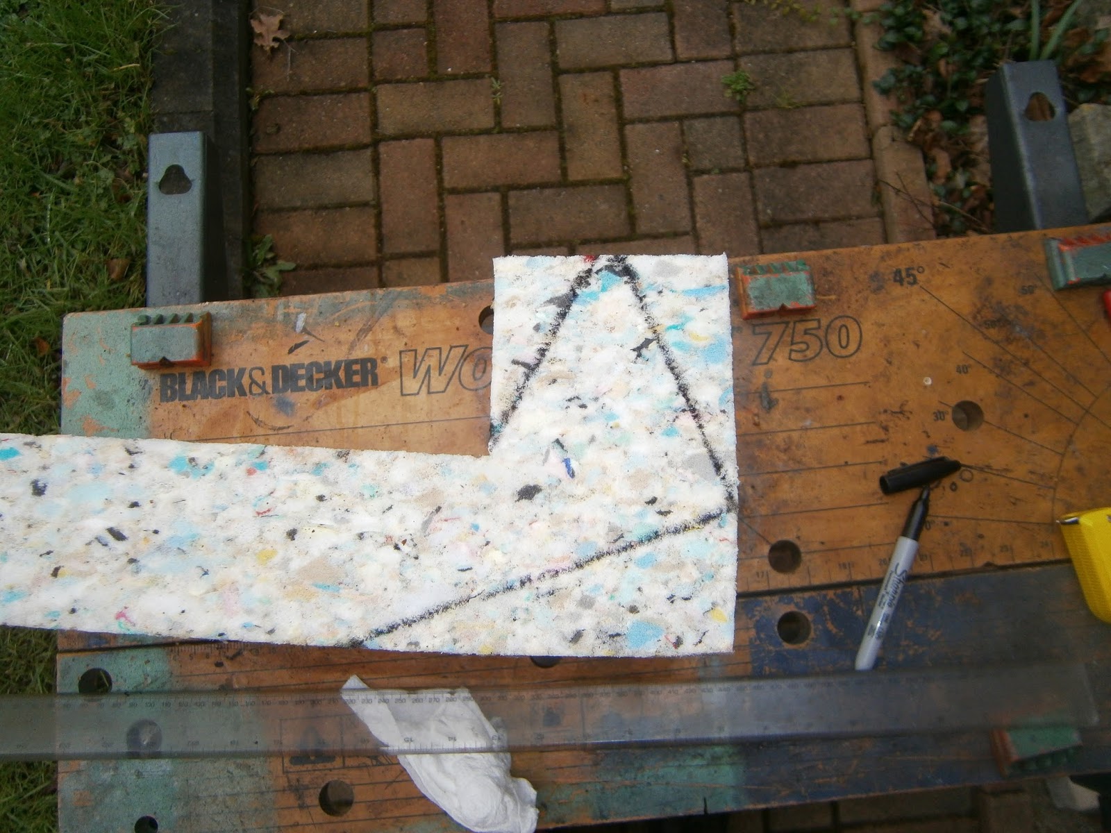
 However, even removing the wheel didn't allow me to fit the chain. I double checked the length and... oops! I hadn't realized that chain lengths specified in the catalogues include the removeable link- I hadn't counted this when I had checked my own chain and including it means that I require a 101 link chain! This is apparently specified for the Fleetstar as opposed to the Starfire (which does use a 100 link chain) although this fairly important fact isn't mentioned in either the '68 or '69 B25 parts lists and nor is it mentioned in the Fleetstar supplement... so who knew! Luckily the supplier was able to send an addition link to allow me to extend the chain. I show here a photograph of my original chain (lower) which has a cranked link inserted giving a total length of 101 rollers and presumably 100.5 links?? The new chain is shown above where the cranked link is clearly missing. Hopefully I will now be able to reassemble the bike!
Original chain (lower) and new chain (upper) Note cranked link and extra roller pin in the old chain.
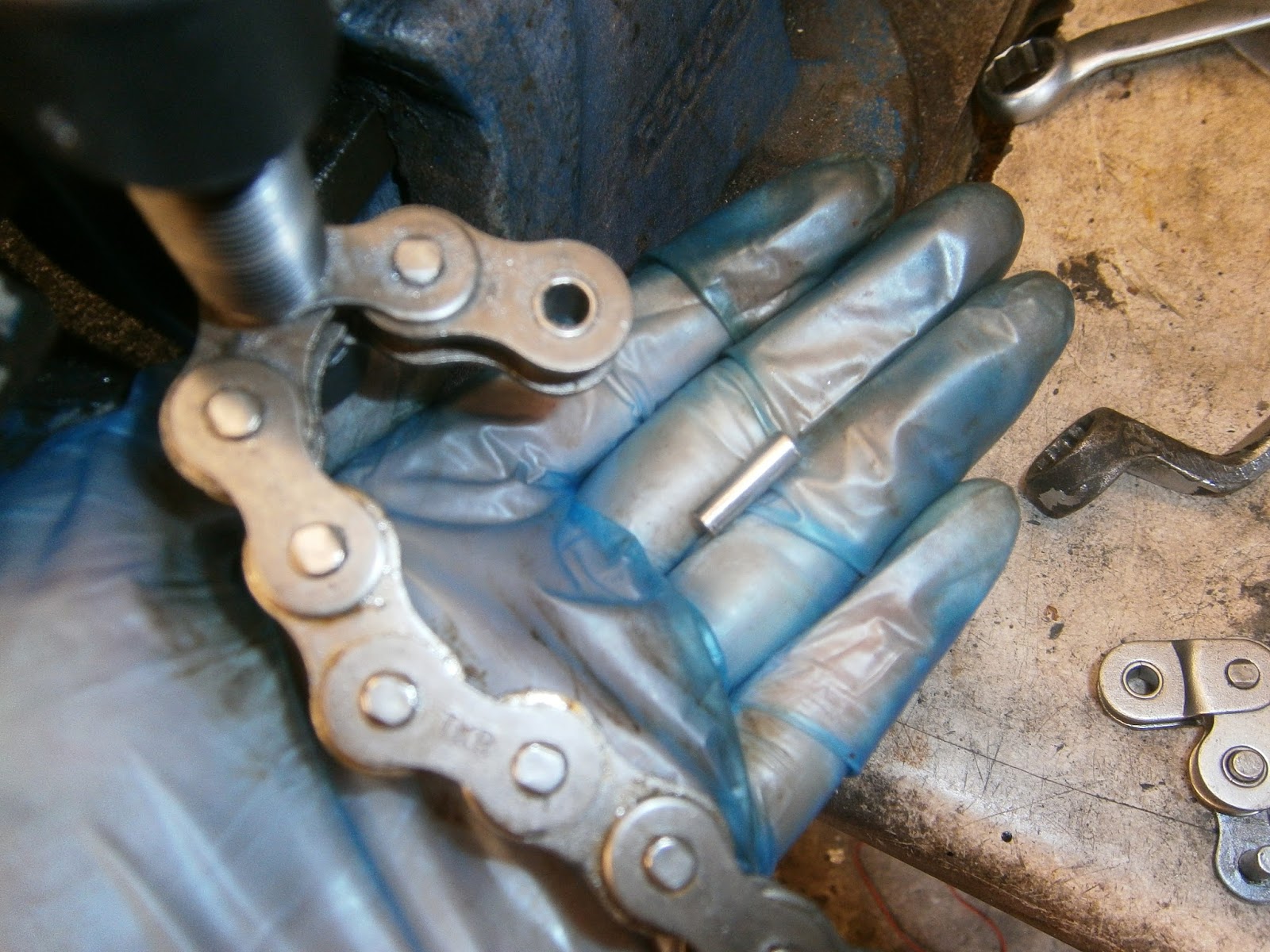
Well the extra link duly arrived and I used a Sealey Chain breaker rivetter to remove the old and install the new (plus extra pin). This tool comes with its own instructions but those from Motion Pro for their equivalent tool are much better- you can find them here:
http://www.motionpro.com/images/documents/08-0058.I8-0058.pdf
The tool is identical.
This is the link in the new chain that needs to be removed and below is the new link and cranked  link that needs to be inserted to lengthen the chain by one pin

I used a Dremmel to grind around the pin to be removed to take off the "mushroom" flare that holds the pin in- this should make the pressing out easier


Assemble the link breaker using the right sized pressure pin as in the instructions- screw in the top bolt to press out the link which will... 
Fall out from the base of the chain

This is the links separated and the new ones with the soft link to be fitted instead


Here soft link in position

and plate loosely installed over the top

The rivetter is reassembled using the grooved and holed plates to press the top plate onto the soft link. I measured the width of most links as 0.6" and pressed the new plate on to a similar dimension..


Installed plate- soft link projects above the new plate so that...


It can be flared with the rivetter once the tool has been modified to substitute the anvils for the two plates.

Completed chain with new links rivetted in.

Both ends of the new chain now join-able with the split link.
 Once the chain was extended, I needed to lube it before installation. The one word/phrase missing from the pack when I got this chain was "O-ring" so I assumed that this is a somewhat old-fashioned chain lacking O-rings. This proved to be correct, but it does mean that lubrication is more crucial. The following is  a method for greasing non O-ring chains, it does no harm to O-ring type but I doubt it does that much good either. Before lubing the chain I cleaned off the transport grease using chain cleaner and a fluff-free rag.


In the old days this stuff was called "Linklyfe"... can't get it now, but this Putoline chain wax seems to be the same stuff.- Stick it on the stove to melt the grease- do this when no-one else is in and don't tell anyone. It can smell a bit- be careful to clean up any spills.

Molten and gloopy
 Carry the tin carefully back to the workshop- put some paper down! Tie a string through one end of the chain
Using the string lower the chain into molten grease, swirl gently and allow to remain immersed in the grease for at least 10 mins.

Bubbles will rise...

Lift out the chain using the string and hang it vertically to drip the excess grease back into the can- this will be messy- remember the newspapers... The grease will set on the chain fairly quickly and dripping will stop.

Add caption
 Having modified and now greased the chain I was able to install it easily- the two ends lined up beautifully on the sprocket.
Chain aligned on rear sprocket
Install cover plate and finally...

Fit split link with closed end facing the direction of movement in normal riding.
 The next problem is to set the wheel alignment. This really needs to be done a few times at each stage but at present- with the brake backplate not fully tightened I checked it anyway using a chain alignment gauge. This clips onto the rear sprocket and the guide rod should then run along parallel to the run of the chain- as here. I had by now cleaned the threads of the adjusters and their nuts so I could just nip them up to the adjusting plates to hold the wheel in this position.


I will recheck as I tighten all the bolts.  Finally I managed to get hold of an original B25 chainguard as this bike had a pattern part. The design underwent a change in 1969 so the guard that my bike should have was only made for a year. This is probably because the mountings (one at the front and one midway along the guard)  allowed too much vibration and so the darn thing always cracked. Consequently there are very few of those around, but you can still get the later type in which the rearmost mounting was moved right to the rear of the chain. This needs a new mounting hole (two actually) in the rear sw arm behind the shock absorber mounting. I drilled and tapped one hole to make sure that the guard would fit (it uses the same front mount).

The guard fitted well although I did need to bend it slightly to prevent the chain making contact at the front.