Search for tasks. Type in a few keywords.

Wednesday, 4 May 2016

Decals

Well the bike is back together and running- it has some annoying habits- idle is too fast and won't slow down- I think the cable is too tight, The motor keeps cutting out- I think its because I'm running it with barely any fuel at present, and the tappets are still too noisy- I will try the new method of adjusting them (details later)

At the moment I'm trying to tidy up its appearance so I'm stripping the nasty paint off the front wheel rim (I will try to bring the chrome back and respray if I cant... hopefully I can get a better finish) and trying to apply some fresh decals to the bike and failing! I haven't managed to get a clear description of all the decals this bike should have had. Certainly it seems from photographs and brochures that the non-Police Fleetstar had a white winged BSA logo on the tank and a "Fleetstar 250" decal on the battery cover and oil tank. I suspect there would have been a couple of piled arms as well as  warnings/notes as well but I haven't been able to find them described anywhere. There seems to have been a lot more on the US export bikes, but as most of these were only required for the US market I can't use them as a guide. I will keep checking but sending a query to the forum failed to proved any more enlightenment. I ordered these twotypes from eBay. The tank winged "BSA" decals were easy- peel and stick; the side panel "Fleetstar 250" were a different matter.
Tank decal- self-adhesive so a bit "blocky" Gold BSA on a transparent sticker

Self adhesive decal- but even more blocky than above as its lettering on a black background which isnt quite the same intensity as the paint colour- clear background decals are nicer.

NOTE to sellers of DECALS- There are (at least) three types of decal- peel and stick, water slide (a little like those RAF roundels that came with the  plastic plane kits we made as kids) and varnish stick They are not the same. The former may be called a sticker, the latter two transfers, but they are all decals. Why oh WHY would anyone even think of selling them without saying what type they are??? Yet everyone does! What's the matter with you all? - Put some basic information in the bloody ads for Heaven's sake!

The peel-off ones are easiest to use- but look worst! They are simple to recognise, removing the backing paper reveals a self-adhesive surface on the back of the design.
Self-adhesive (vinyl cut) decal. As it comes (upper) and partly peeled off (lower). Note sticky surface on the back of the decal 
Apart from the peel-off sticker type, fixing the other two is not straight forward- and its not "easy" despite what it says in the listings. It needs instructions (which are always absent) and it needs practice; if they are the varnish-fixed type then you need to know to get the right stuff in before you try. Most descriptions of the method direct you to US varnish brands- The usual type are actually floor varnishes (eg Minway high gloss fast drying polyurethane varnish). I think there was a Johnson equivalent on sale in the UK (called Klear or Future?) but no longer- although it is available now repackaged for modellers in smaller amounts. I suspect virtually any polyurethane would do- but then you don't want to risk your decals trying any old varnish do you... ? I have just buggered two Fleetstar decals purely because of lack of information from the seller- and the fact that they were closed for half the normal working week and so weren't there to help when I needed them. ..  overall NOT a happy bunny at all.

Varnish-applied type- note the front and back mounting paper (above- as it comes) and below with part of the backing paper removed (front paper now down). 
Varnish-stick decals have two backing papers, peeling off the back one reveals a non-adhesive surface, the decal itself is still attached to the front sheet but it is upside down (see lower decal above).

Water slide decals- no picture sadly- Also have two backing papers, and when you remove the first you also find a non-adhesive surface - but in this case the the decal is uppermost- ie the right way up. It is usually still attached to a glossy backing paper on which it can slide when wet so it can be eased off the backing paper and onto a wetted paint surface..

... 24 hrs later, calmed down! Classic bikes of Cheshire did respond to my missive and offered an odd fixing process... I don't think they realised that the decals they sold are for varnish fixing. They offered a replacement but I had already sourced a cut vinyl self-adhesive replacement which is self adhesive and thus much easier- although not of course original at all. I fitted both decals but the side panel was looking a bit ropey so I resprayed that using black gloss Aldi metal protection paint first- covers really well and goes straight on over metal. Takes a couple of days to harden fully but very pleased with this- much better than Hammerite which I always preferred, but recently it seems to have an unacceptably low pigment content and takes ages to cover.

I also replaced the tank rack screws and fibre washers beneath each leg. I used smaller washers so that they didnt show beneath the legs. Lining up the screw heads gives a nice neat appearance.

Wednesday, 20 April 2016

Jobs I hadn't expected to have to do again (1) ! Fitting fuel tank, taps and filters

Well the bike is back together and running- but having run the motor for a short while I was surprised to see that the new in-line fuel filters I fitted were trapping quite a lot of sediment. Thank goodness I had fitted them!


This was a surprise as I had thoroughly cleaned the tank! However I hadn't treated it with rust remover/converter as I usually do so I assumed that this was some missed corrosion that was now flaking off (serves me right for taking a shortcut!). I decided to remove it again and do the job properly. Guess this will also give me more room to fiddle with the tappets and try to decrease the top end rattle- so this is the next job.

Removed the tank- disconnecting the fuel lines- this is where I got my surprise- this "sediment" turned out to be a brown cloudy liquid- presumably water-based as it sank in petrol. A bit of a surprise because I was sure that I had dried the tank thoroughly.- I eventually tracked this down to water that had entered the vented fuel cap during the tank cleaning process- I had forgotten to cover the tank filler hole with plastic before fitting the cap to stop water entering the cap itself (Duuuhhh!). At least this means that the engine isn't about to be messed up by rust particles though. In any event I decided I had better repeat the clean and de-rust the tank properly- felt guilty not having done it in the first place.
So off with the tank- fitting the bungs below in place of the fuel taps and using the Rustbuster Tank-kleen and ball bearings again.
Bungs blocking off tap holes


Cleaning was uneventful- for de-rusting I use this stuff Deox C-  I got it from Frost restorations and its darned good stuff- Its a harmless white powder that's easily disposed of ...
Don't put Deox C in your coffee!

... and I think its active ingredient is just 10% citric acid with maybe a little sodium metabisulphate and/or phosphate added.  I will try mixing some up from first principles for next time because citric acid is really cheap! I like to mix up a 10% solution of this deoxC and then make sure that it reaches every part of the tank for at least 60 mins- so I support the tank  for an hour in every orientation- treat base for 1 hr- each side for 1 hr and the top for 1hr.  Finally I top it up with water and let it stand overnight so that everywhere gets exposed to the more dilute solution.
Below are the before and after pics for the tank filler

Inside tank after cleaning

... and after de-rusting- much better.
Having refitted the tank I found that the taps were still unacceptably stiff. I had hoped to avoid having to buy new taps but since these are so hard to turn they hurt and risk straining the joints. They don't even shut off fully anyway so I will have to bite the bullet and order a new pair. Getting replacement brass taps was a bit expensive so I've gone for standard Triumph/BSA 1/4 BSP to 1/4 BSP chromed items- ethanol resistant anyway. I dont think that this bike has a dedicated reserve tap as such. I think the fuel level drains down the remaining fuel becomes separated into two parts each side of the central divide.  It then just empties which ever of the sides happens to be connected to the carb- the other tap then empties the remaining side thus providing the "reserve". This means that  obviously if you run with both taps open then you will have no reserve when you run out and secondly that each tap needs to be able to drain to the bottom of its "side" of the tank- in other words I need 2 of what usually passes as a "reserve" tap.

I got a pair of taps for about £20 and both ethanol resistant- also a bonus.

However- the more observant amongst you will recall that the BSA taps are 1/8 BSP (duuuuh!). Still- even with the necessary adapters, these taps are still about half the price of bronze 1/8 BSP replacements.


The B25 fuel tap - at least in '68, was an all brass affair. The tank base is tapped at 3/8 BSP and into this fits a brass adapter- 3/8 external and 1/8 internal BSP threads. This adaptor also carries the in-tank-filter. The tap screws directly into the adapter and has no filter itself. The tap and adapter are so designed that they seal via flat surfaces both between adapter and tank, and between adaptor and tap. These can be easily sealed with fibre washers.

Later taps (like those I bought) are threaded 1/4 inch BSP on both sides; they have an integral filter, and screw into an adapter in the tank (3/8 to 1/4BSP) but seal onto the thread of the adapter with a locknut and they have no flat flange. I see this as a retrograde step in design as sealing threads is never going to be as reliable as sealing between two flanges. In order to get a good seal on these later taps BSA and Triumph then moved to using the metal reinforced sealing (bonded sealing) washers (aka Dowty washers). These consist of an inner ring of sealing rubber (or rubber-like) material bonded to an outer metal ring. The sealing inner the inner ring  can fill in the grooves of a thread and provide a seal.

New tap, flat and Dowty washers. Note sealing tape on the threads but this should be applied AFTER the washers are seated.
One added complication is that  there are two types of this sealing washer- both apparently and confusingly called Dowty washers! The true Dowty washer has a sealing element that is  thinner than the metal ring that surrounds it. This means you can bolt a nut right up to the washer and the edges of the nut will not actually contact the seal itself. The second type are known in the USA as Stat-o-seal" washers, and in these the sealing insert is thicker than the metal washer that surrounds it. Screwing a nut up flush directly against this type washer would rip the sealing element, and so stat-o-seal washers usually require a second washer between them and any nut which might otherwise damage the seal. Presumably these have to be closely fitting enough that the washer will still compress the seal... but this does raise the question as to how a Dowty washer can ever seal because its sealing ring is presumably never compressed??? Triumph and BSA apparently used a second washer between tap locknut and seal so I'm guessing these were the Stat-o-seal type??? I have ordered a pack of "Dowty" washers- but not the actual BSA parts, so time will tell which sort actually arrives. Yes, you've guessed, I ordered before I had discovered these subtleties!

All of this means that in order to fit these new taps I need a 3/8 to 1/4 BSP adapter and a 1/4 inch nut-and-spigot to link to the fuel pipe below. I will also

Fitting the new tap
These threaded taps can leak- trust me I have had too many leaky taps in the past! I seal them now using a belt-and-braces approach as below.

Put the fibre washer on the tank adapter and apply two turns of PTFE sealing tape. Trim this off at the top and bottom so that its not flapping about in the tank or obstructing the fibre washer. Check the tank base flange is clean and then screw the adapter fully into the tank and tighten.

Push the flat washer and then the Dowty washer onto the tap down to the locknut which should be fully screwed down.

Apply two turns of PTFE sealing tape. I used the yellow gas grade (not sure why) but make sure the tape is clear of the Dowty washer

Screw the tap into the adapter in the tank- it doesn't need to go in fully just a soft contact with the washers. 


Position the tap in a convenient position and tighten the lock nut up against the adapter, compressing the Dowty washer making sure the tap doesn't turn out of position. Fit the spigot and nut- this is a taper seal and requires nothing extra to seal properly.

Leak-free seal- job done and very pleased to have two functioning and leak-free taps on the tank at last!.


need a Dowty washer (1/4 BSP) for each tap.

Wednesday, 13 April 2016

Recommissioning- those blasted tappets and lengthening a pushrod!


The bike is back together now, but before I try to fire it up I wanted to check the tappets. These use the eccentric cam system and I've never done these before. I have two Jubilees queued in the wings and these use the same system so I'd better get used to it! The principle here is that turning an eccentric cam within the rocker shaft moves the shaft up and down and thus moves the tappet closer or farther from the valve stem head. In order to keep tabs on where the shaft is there is a flat on the adjuster


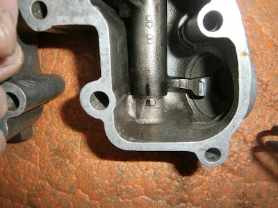
Rockers inside the box. The rockers consist of a hollow rocker shaft visible here and through which is passed an eccentrically mounted cam on a solid internal shaft. There are washers on each end of the shaft to allow movement without wearing the ally rocker box case.


This is the internal shaft removed from the hollow rockers which could then be lifted out. Note the cams which move the rocker


The eccentric shaft screws into the back of the rocker box and is usually prevented from rotating by a lock nut but this has been removed here.


The other end of the eccentric shaft carries a slot so it can be turned and a flat to monitor how far it's been rotated with reference to the cam position. If everything works out perfectly then when correct rocker clearance is achieved the flats should face each other across the rocker box as shown here at app. 3 and 9 O'clock

There is a nice video here.

The trouble is all the sources I have found just reproduce the same stuff from the manual and no-one really tries to expand or explain it: For instance, the books all say that the flats should be in the vertical position facing each other before starting... Well they won't be will they? They will be in whatever position they were last set? So should they be turned vertical first and if so in which direction? Does it matter?

Secondly the sources stress that the rockers should be adjusted by turning them inwards -towards each other- they don't say this but it would be clearer to say "turn the inlet adjuster clockwise and the exhaust adjuster anticlockwise" ... if indeed that's what they mean! When adjusted the flats should be still in the half sectors facing towards each other across the rocker box- an ideal adjustment being 3 O'clock on the inlet and 9 O'clock on the exhaust for instance.... unless you have an early motor ( before C25 2050) in which case this is all reversed... turn the adjusters the other way and ideal adjustment is then 9 O'clock on the inlet and 3 O'clock on the exhaust... that's not confusing at all is it??? (Luckily, the early rocker boxes carry a spring washer under the eccentric shaft lock nut and further, the early rocker boxes have an internal strengthening rib in the centre of the "horse-shoe shape which is missing or machined out of the later type). Mine is a B25 motor and the number is higher than this, it has no such spring washer and no internal rib so all signs point to it being of the later type,

Obviously as you turn the shaft you will cause the shaft to advance into the threads on the far side of the rocker box. Eventually you will run out of thread and the shaft will be screwed tight into the box. At this point you need to turn the shaft back 360 degrees to restore movement. Although this will restore rotation, does it affect the amount of adjustment possible?

OK here is what I have gleaned from taking the rockers apart: The eccentric does indeed move the rocker shaft (and thus the tappets) up and down... BUT it also moves it to and fro; towards and away from the cylinder centre. When the flats are facing one another and within 180 degrees then both rocker shafts have been moved inwards toward the cylinder centre- and I am guessing this is when the tappet pads make best contact with the valve stem heads. The movement isn't large and I'm not convinced that it would make much of a difference, but I suppose "best is best". The requirement to have the flats vertically at the start is to make sure that the shafts are in this stage of their rotation, I presume just in case there is so little clearance that its not possible to turn the shafts back through the vertical position to make the adjustment if you are on the wrong side: Well this is getting to my experience, and I can say that so far its my opinion that there is fat chance of that! In my experience there is so much clearance that you can always turn the shaft a full 360 degrees to get the flats on whatever side you want so this initial setting doesn't seem important.


I'm trying to find out how much movement is provided by the cam. Here the flat on the adjuster is fully outwards and I marked a line before...


Turning the flat through 180 degrees to be fully inwards. The shaft has moved over by about 1mm

Testing with a scribed line (and also with calipers) suggested that the cam provides about 1mm (25 thou) of movement. This then is my problem: I was able to successfully set the exhaust at 10 thou- but the inlet was far too wide- best I could do was 18 thou and this was with the flat fully downwards!


Best settings I could get: Exhaust (right) is just about OK but angled more down that I'd like but the inlet (left) is horizontal at the bottom- this corresponds to max adjustment and it was still nearly double the clearance needed.

I had hoped that the rocker shaft/rocker cam might be tapered so that as you screwed the rocker cam shaft into the rocker box it would increase the amount of adjustment possible by one revolution. Sadly this seems not to be the case and the rocker shaft seems to be straight bored, you get the same (inadequate) amount of adjustment in whatever position the shaft happens to be across the box.

A little research showed that several others have reported difficulty in getting the right clearance on other forums. Although others have posted such a problem, I cant find anyone posting the solution! In my case its not a large discrepancy, the motor will run, although its difficult to start, runs poorly and only at rich mixtures (possibly as the inlet valve isn't open for long enough) and the tappets sound awful- but it does run. The bike was running before although it did have noisy tappets even then- I haven't touched carburation or timing and I still have very decent compression at 145 psi.

So suggested causes for this problem are :

1. Too thick a gasket at cylinder base or below rocker box- I have fitted only the paper ones so presumably this isn't the explanation. I have fitted a new head gasket but again I believe this is the correct thickness.

2. Too short a valve stem- I have fitted GS valves and although I didn't measure them, they should be OK. Of course they have been in storage for years and so could conceivably have got mixed up- I hope not as this would mean stripping everything down. Note head seat erosion or re-cutting should decrease tappet clearances not increase them.

3. Wear in rocker valve operating pads. Certainly there was some but I didn't think it would be this bad and it wasn't obviously worse on the inlet vs the exhaust.

4. Incorrect push rods. The push rods are not of equal length in this motor and it seems that BSA changed the push rod length a few times. They could be simply wrong- or possibly switched as the inlet and exhaust push rods aren't the same length. I'm certain I put them back the way they were, but I didn't measure them while they were out (now I wish I had). The exhaust rod was still marked red, however it does have the look of a home-made red mark. I guess I can't be sure a PO didn't switch them and mark the wrong one?

However, if the push rods were switched then this would only make sense if the inlet rod is longer than the exhaust; so that a shorter exhaust rod would then give excess clearance if incorrectly fitted to the inlet valve, but the longer inlet rod would require less adjustment to seat correctly on the exhaust. After that its a question of finding what the lengths should be- and here I hit a problem- the only reference I can find is in the Rupert Ratio book which incidentally gives quite a lot of detail about the eccentric - in more ways than one- adjusting system. This gives three entries that might be relevant; the C25 motor (both up to 2050 and after engine no 2050)... and for this the exhaust is actually longer so swapping wouldn't account for the problem. However he also lists the C25/B25 (meaning what as distinct from the C25 above??) which he says, has had several different push rod length during its production. To find the right one (from scratch?) he suggests starting (?) with an inlet rod of 6 15/16" and an exhaust rod of 6 7/8" - i.e. an inlet rod 1/16" (62 thou) longer than the exhaust so the theory lives on! There are other bikes listed but the C25/B25 the only case of exhaust being shorter than the inlet.... is this an error I wonder? i have also never come across the concept of choosing your own push rods but I guess it depends on how much bespoke engineering you require.

Plan-

1. Try to swap push rods- it may be possible to do this without removing the head if I can find a way of levering the valves down to provide enough clearance to detach the rods from the balls on the rockers.

2. Fit a longer rod for the inlet. This can be done by lengthening the existing rod by inserting a metal shim below the steel cap or cutting down a longer rod- e.g. from a C15. I'm not sure how you work out just how much longer you need to make the rod though. Rather than ruin mine, and since I am on a learning curve, I have ordered a used B25 inlet rod to experiment on.

3. Fit a lash cap (valve stem cap) this goes over the top of the valve stem and reduces clearance. I have found these made for 5/16 valves by CCM Britain ltd although RGM Norton also do them. They are obviously not std for the B25 so I will test them for goodness of fit and effectiveness in clearance reduction.

OK so much for the worry- time to do something. I was unwilling to take everything off but in fact if you remove the nuts the rocker box can be raised sufficiently to allow the push rods to be removed.


raise the rocker cover and...


... the push rods can be finagled out.

I measured the rods as best I could (steel ruler-) Obviously this isn't as accurate as the daft values given by BSA but it was clear that the exhaust was actually shorter than the inlet rod by about 1mm at 174mm in length. Swapping the rods cannot therefore be the explanation.


Measuring the push rods.


The ends of both rods have taken a bit of a hammering over the years, and although neither was bent (rolled well on a flat surface) its possible that wear at the end has maybe shortened the rods. According to Rupert Ratio's book (and converting the daft fractions to mm) then the rods should be; Inlet 176.21mm, exhaust 174.61 mm. It thus appears that both my rods are around 0.5-1.2mm too short, (although I can't measure them to that accuracy!). This fits with the max adjustment in the eccentric being about 1mm as well and explains why it has run out in the case of my inlet which seems to need about 1.2mm. Mr Ratio also says that the rods can be lengthened by inserting a shim below the steel end cap.- of course to do this you need to know what thickness shim which presumably should be in the range above... and how to get the end caps off the rods!

The exhaust rod end cap turned out to be only a loose fit! I'm pleased to have discovered that because I hadn't noticed during my initial reassembly and I'm sure its not right. At the least cap movement would make the bike noisier than it needs to be and at worst could come off during use!!


Exhaust push rod end cap just slid off in my hand!

Sadly its the inlet rod I'm more concerned about ans this was a really tight fit. It wouldn't pull or tap off so I reasoned that if it had been loose like the exhaust, then perhaps it had been Loctited on. I therefore tried heating it as Loctite will only let go when hot... no joy, if anything the fit got tighter. Finally, I put the rod in the freezer for 30 mins and then returned it to the soft jawed vice- the cap no knocked off easily so I guess this is the way to go.

Given the reasoning above- that the movement in the adjuster is about 1mm, the rods are 1.2 and 0.5 mm too short and that even max adjustment doesn't generate a small enough clearance, I reasoned that I could extend the inlet rod by about 1mm and the exhaust by say 0.5. This was actually a moot point because I only had mild steel sheet at 0.75mm (22G) so that was going to have to do for both. Mr Ratio doesn't say what sort of metal should be used as a shim but I am hoping this will last a decent time. Perhaps a small (0.5mm) diameter hardened washer would be better?


My metal 0.75 mm thick

I cut a 0.5 cm square of the metal with tin snips and then ground this down to a rough disc shape that fitted easily into the rod end cap


Roughly ground disc, its an easy fit in the end cap.


Obviously I need this to be flat so I tried to remove any burrs with a fine file and then hammered it onto the anvil section of the vice before slipping it back inside the cap and slipping that onto the push rod. The inlet needed to go back into the freezer before the cap would fit back on.


Inlet rod extended. Before I removed the end cap I had scribed a line on the rod. This is the refitted cap with internal shim and the original scribe mark is clearly visible; the rod is lengthened by 0.75 mm or so.

Having modified both rods I test fitted them, I wasn't altogether sure that the exhaust rod needed a shim at all and I didn't want to Loctite it in until I knew it was going to work. Once again make sure you have actually engaged the rods in the cam followers at the base of the pushrod tube- harder to do than it sounds, before lowering the rocker box fully to engage the ball ends of the rockers..


I should have thought of this earlier- a mag pick up tool lets you position the rods easily beneath the ball ends of the rocker shaft and fitting was a doddle compared with the last time.

I tightened down the box using half of the nuts and checked clearances. This time I was able to set both valves at the desired clearance and with the flats in the inner section and facing each other. One point to note though is the desirability of having the end caps firmly fitted to the rods. As I removed the exhaust rod to Loctite it, it simply fell apart and the cap and small shim plunged down the push rod tube.


What no cap! Shock horror! The cap has vanished.


A few moments of panic later, as I recalled that the push rod tube isn't fully open to the crankcase at its base, I was able to fish both the cap and shim out again using the magnetic pick up tool.


I reassembled the exhaust rod, coating the base of the shim and the end of the rod in green Loctite 603 retaining compound. This is a pretty good "stick" but I left the rod for 24 hrs to be sure it had gone off before reassembling. So final refit tomorrow. I hope the box gasket will still do its job as I haven't got another. I have been careful not to disturb it and I remain hopeful that I can avoid yet another strip down. I am hoping that the lash caps will arrive tomorrow. Although I don't need these now I still want to assess their suitability as a solution before I put everything back together.

Note added- Put the bike back together again- remember to check pushrods engaged in cam followers- mine weren't (...again!), but eventually sorted, tappets adjusted nicely and I was able to run the bike enough to warm it up and adjust the carburation- seems to be idling nicely now if maybe a little fast, so all good.

The lash caps arrived too late for me to check them but they look like a simpler solution to this problem although they decrease valve clearance by 40 thou (just over 1mm) so might need to be ground a little depending on the amount of excess clearance encountered.

I had to revisit the tappets using a different approach to setting the clearances. In fact this seemed to work better so see my next posting "Jobs I hadn't expected to do again: tappets".

Wednesday, 23 March 2016

B25: Refitting the head and barrel. Oil filter swap and sump


Having restored all the threads on these studs 26 tpi BSF and BSC on the 1/4 inch and 26, 22 tpi on the 5/16 I fitted all studs back into the head. I have decided to use the second head as this one hasn't been skimmed at all and so has more life ahead of it.

Steel studs going into ally should (I believe)  always be lubricated- either with oil, or in this case Loctite threadseal 2701. I applied this to all threads and then screwed the BSF threaded ends into the head. I used the stud remover to tighten all to firm hand tightness, they will grip through the upward tug of the nuts when these are tightened rather than the twist of the steel stud in the head and so studs don't need a lot of torque into the head itself.

I found that I was lacking one of the longest 1/4 inch studs and made a spare one using 1/4 inch stainless steel rod.- Note from experience - don't try threading stainless unless you have HSS taps/dies! I simply blunted the carbon steel cheapo versions that I had and needed to order  the real-deal kit.

Head steady in place- two washers underneath each side to act as spacers
I ended up making three new studs but the rocker box went on fine after that, tightening small nuts to 7 and larger ones to 10 ftlb respectively. I had been concerned about the state of the cylinder base gasket and was also worried that taking the head off might have disturbed it anyway so I decided to renew it as well.


The barrel pulled off easily, here using wood strips to stop the piston flapping about and getting damaged.
Bottom of barrel- signs of base gasket having leaked- I recall it was a bit oily about here so definitely a good idea to pull the barrel. Bore looks good- some original honing visible and no sign of a ridge at the top.
Bottom of barrel cleaned...

... and the top

Barrel cleaned up nicely with brass wire brush on the Dremmel, careful to get the burnt on carbon off the top cylinder spigot and around the liner base


Given the evidence of leakage I decided to take a leaf out of the Lotus book and use a gasket sealant - in this case Wellseal. Lotus use this on all gaskets and I think its a good idea here. If its good enough for Mr Chapman its got to be way good enough for the likes of me! Paint it on to the barrel and then apply the gasket


Gasket bedded into Wellseal


Then paint the other side of the gasket...


... and check that the oil holes are not obstructed.

It was at this point that the best laid plans etc etc -anyway they came unstuck: In order to install the barrel I needed to compress the rings. If you are gifted with a rock hard grip and insensitive calloused fingertips you can probably do this by hand- I wanted to use a ring compressor. I have the Laser 5066 Universal motorcycle piston ring compressor kit which should cover this piston size... and it does... but unfortunately the position of the studs means that the clamp cant be fitted!!! Much swearing and aborted attempts later (all the while with my Wellseal going off) there was no alternative but to remove the front stud to gain access and refit it later.
Front stud removed

 The ring compressor then fitted a treat BUT... the stud is wider at its base than than at the top and cannot be inserted downwards through the barrel so fit the compressor and insert the stud as you lower the barrel down...
Compressor in place- just need to...

 Feed the stud in (coarse thread down) from the bottom of the barrel and slip it into alignment with the hole in the crankcase before...
 Lowering the barrel- with the compressor in place its now a doddle
 Remove compressor, lower fully and lastly tighten the stud back down into the crankcase (oiled thread)
Push rods on tappets and angle for their respective rockers.
 Fit push rods into the tappets - intake is at the front- don't mix them up. Apparently the exhaust should have a red top- mine was marked but poorly. Fit a new head gasket - I think these can be reused- there seem to be a lot of used ones on Ebay anyway, but I think they would need annealing. I just bought a new engine set so I would have everything I might need.
 Lower on the head- you need to fit this at first positioned on top of the push rods but facing out to the left of the bike. Then you can swivel it back around the push rods and line it up on the studs. Note new head gasket in place.
 Check the rockers engage on the pushrods as the head comes down- here the inlet...

...and here the exhaust. You will need some form of hook tool to position the push rods as the head comes down, I used a pipe cleaner. This job would be easier with three hands and slender fingers but it can be done. You can get some movement on the rockers by depressing them with a finger through the rocker cap and then lowering them back onto the top of the push rods before the head is fully down- might be best to make a wooden spacer about 1-2 cms thick to support the head while the rockers and push rods are in this "sweet zone" where there is just sufficient vertical room to lift the rockers enough to let you move the push rods underneath, but tight enough that lowering the rocker then engages the rod top and holds it in place while you do the other, and of course lastly remove the spacer and lower the head.

BUT- all this fiddling about can cause the base of the push rods to jump out of the tappet/cam follower at the bottom- and as this is now invisible the only way to check is to fit the head loosely hand tight is good enough  (don't need to torque down) and rotate the motor to check both valves operate and in the expected sequence. On my first attempt I had somehow dislodged the inlet so it is worth checking.


Finally torque down the head- as I suspected during dis-assembly, it is impossible to torque the two 5/15 nuts on the studs recessed below the rocker box... even with a crowfoot spanner. I torqued down what I could and just made sure these seemed to be "as tight"


You can make a compound torque wrench like this using a socket adapter to attach a combination spanner to the torque wrench and the C end to slip onto the nut- no good for tightening really but just to check final torque. I still think this idea has a lot going for it but as the torque is now measured some 15 cm from the actual nut head I suspect the reading I'm looking for would differ- the maths of this defeated me so I just went for "tight".
Before I could finish the bike, I needed to sort out the leaking tank. This has a filter socket combined with a banjo union at its base. The banjo is sealed by two washers - I had expected copper but they are specified as "fibre" in the parts list (The Starfire shown)
Banjo washers are shown with different numbers but they have the identical BSA part number so in fact are the same.
 The washers should be the same, but in my case there were two different washers fitted of different thicknesses.
Note different washers and hole in filter gauze
 There is also a hole in the filter at the base- this would let any crud straight through so the filter will need changing. It is possible just to get the gauze filter (RGM Norton have one that should fit) but this is about half the cost of a new unit and still needs soldering on in a neat and tight fashion- it seems easier just to replace the lot.
Thread in base of oil tank

...and here is the rub! The filter unit can only screw into the base of the tank so far- eventually it screws up hard against the end of the threads. At this point the banjo section is left protruding but the washers have to seal tight before you run out of thread- and in my case they hadn't. What this means is that the thickness of the washers is critical- anything too thin will never be able to seal - and this seems to be my problem.

I ordered a new filter plug and two new fibre washers- however I also found a metal replacement washer pair on offer which are apparently reusable with care so I ordered two of those as well.

I


Nub of the problem old washer right- thinner than new (left) either from new or through over-compression. New washers were 2.6mm, the old ones 1.4 and so that's 2.4 mm of thread saved on the filter plug fitting

New filter plug in position with fibre washers.

The "metal washers" turned out to be two large Dowty washers with a gratifyingly thick rim. I havent fitted these as yet as the fibre ones arrived first but I may do so later.

It seemed churlish to have come this far and not checked the sump so I undid the 4 x 3/16 WW bolts holding it and allowed the oil to drain into a container.
sump retained by 4 x 3/16 bolts. Bit nasty and a couple of gouges.

Sump removed, lots of gunk trapped around the edge of the gauze and gasket 

Remove gasket - note crud around gauze and...

Clean up the filter mesh. I used my sonicating bath and it loosened the crud very nicely.
 The sump is obviously on the bottom of the motor and so the plate and the bolts are a prime candidates to collect grit- and I found quite a lot worked into the threads of both bolts and bolt holes. This will wear them in time so I cleaned all the bolts and washers in the sonicator and cleaned out the threaded holes in the crankcase with carb cleaner spray and a pipe cleaner
The underside of the plate had obviously been scraped at some point resulting in some grooves and ridges. I filed these as smooth as I could get them and then treated the sump plate to a new coat of VHT alloy effect paint. I refitted it with a fresh gasket, using copaslip on the bolts.

The rest of the reassembly went gratifyingly well: I used copper RTV silicone gasket to help seal the exhaust into the head. Even the problematic right footrest turned out to be no problem- it was a taper fit not a splined fit and after cleaning both tapers and the bolts it reassembled without play.