Stripping and sorting the CARB
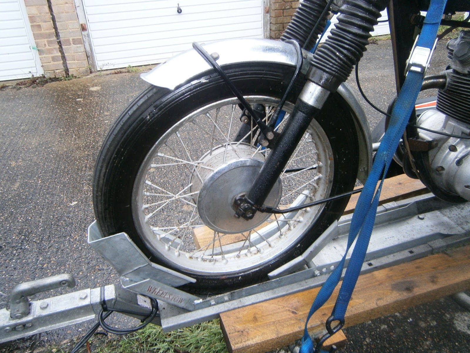
When I got the bike it would start but was stuck on full revs, even so the throttle cable did seem to be moving although without effect. It seemed sensible to strip the carb. It's mounted in front of the down tube on the frame and there does seem to be enough room to remove it without detaching the cables or removing the tank first- bit of a struggle but it worked! I suspect the tank will need to come off for refitting though.
 |
| Carb mounting bolts 7/16 Ww |
 |
| Stripping the carb- detach the pancake air filter- two clips linked by a screw, it then unfolds and the internal gauze filter just lifts out. I couldn't unscrew the back plate from the carb throat. |
 |
| Unscrew two cap nuts and pull out throttle slide- this was really stiff! Screws stored in top of carb body for safekeeping. The throttle slide seemed to be dirty with some greasy deposit(Possibly gasket goo?) and this I think explains its stiffness. |
 |
| I couldn't unscrew the pancake filter rim so went on to unscrew filter bowl- two screws only, fairly sticky deteriorating and nasty gasket beneath |
 |
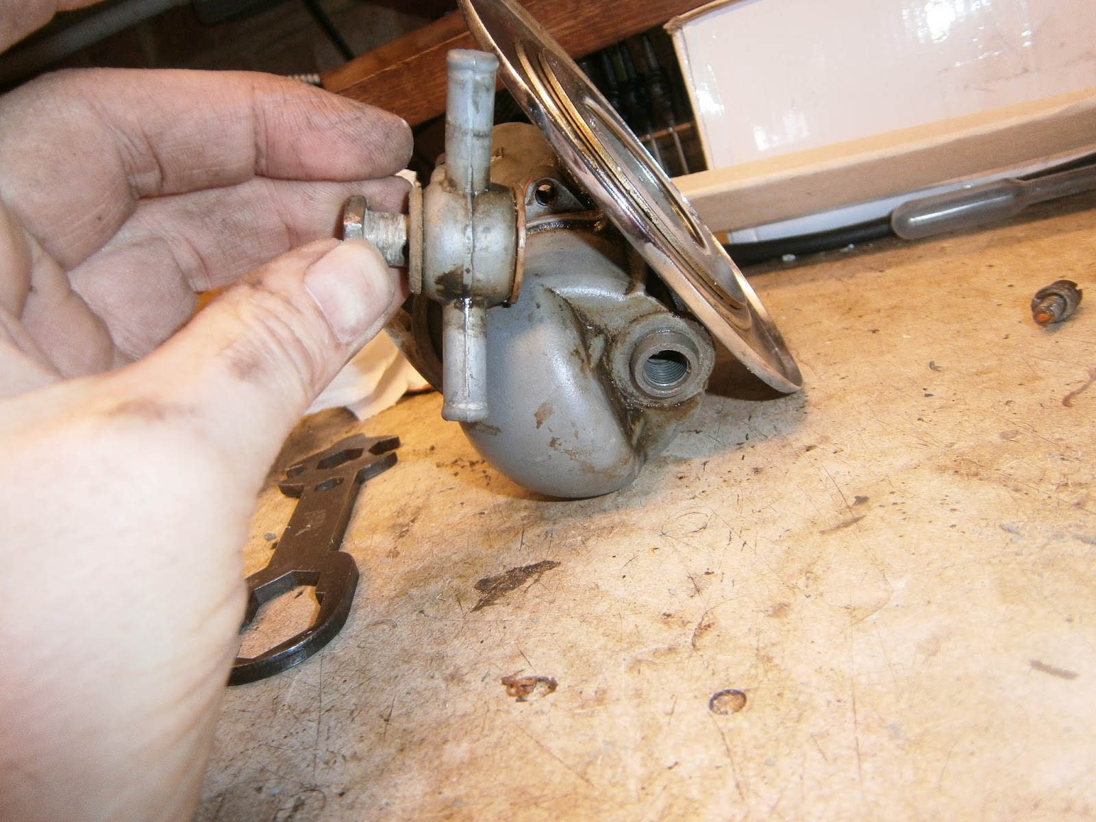
| Remove banjo union by unscrewing the centre banjo bolt. |
 |
| ... and powdery gunk inside the trap! |
 |
| I'd removed some already!- lump on finger. |
 |
| ... and I'm pretty sure there should be a hole through this fuel inlet in the banjo union! |
 |
| Muck in the other side too although still passable. Cleaned out both with a pipe cleaner. |
 |
| Float was dirty but not punctured. Float needle valve looks very tatty and should be replaced. note dirty banjo bolt behind. |
 |
| Main jet and jet holder in base of body |
 |
| Jet unscrewed- I don't know much about carbs but I'm pretty sure all this gunk shouldn't be there! |
 |
| Carb parts, the routes of the channels in the body are visible here as horizontal bulges in the carb moulding (RHS), the upper channel (above main jet passage) is the fuel intake via the small hole top right that communicates with the float chamber when the carb is assembled. The bottom passage (with the blocked hole) is the air intake, blocked to float chamber but open at the front of the carb. Fuel is regulated by the internal pilot jet (not visible but positioned in the channel above the brass plug!) and these two materials mix under the brass plug. From there they exit via the central channel to emerge in the carb throat through two holes: one under the throttle slide and one between slide and motor. These supply fuel when the throttle is closed and at low throttle openings respectively. |
The system of passageways in the carb is visible in the figure above, the bulges in the casting that run horizontally left to right convey fuel from the pilot intake (upper channel in this pic) and air from the front of the carb (lower channel). These mix beneath the brass disc and then out into the motor through two small drillings in the carb throat which are fed via the central channel which connects to these exits when the carb is reassembled. I have annotated the picture below for clarity...
The pilot system can be cleaned using carb cleaner and steel guitar string (high E) ( which is smaller than all the jets in the carb. Remove the pilot air screw and carefully poke the wire into the hole, you will need to jiggle it a bit to get it into the hidden internal pilot jet and maybe to shift any crystallised gunk in there.
Make sure that the wire penetrates far enough to go right through from the pilot air screw, beneath and past the brass disc to meet the wall of the fuel channel on the other side and then squirt carb cleaner or compressed air into the pilot airscrew hole to remove debris out of the fuel intake hole, not back into the pilot jet! When clear (and fully assembled), squirting carb cleaner into the pilot airscrew should allow cleaner to exit through these two small holes inside the carb throat, plus the air intake hole (carb front) and the fuel intake hole (roof of float chamber). Block these latter two exits with a finger when testing as they are quite large and most cleaner will simply run away through them. Blocking them makes it easier to check that cleaner is also exiting both of the smaller holes in the carb throat.
 |
| Hold jet holder loosely in vice and unscrew needle jet, mucky again. |

|
| Mixture screw on right, throttle stop on left. I screwed both in completely to gauge their position before removing them- Air screw goes in 1 turn and throttle stop 1.5. Both were very stiff with threads full of red goo! Carb number 928/300. I know the 9 refers to a 900 series, and the 28 to the choke size. 300 is apparently a build number but its not like those of other B25s I've seen which seem to be a single number. According to the Burlen site: "928/300 is a Mark 1 900 series, with a 28mm bore, right hand adjustment, for a 4 stroke petrol engine." so not a lot of information there for jet sizes etc! |
I cleaned the carbs by spraying carb cleaner through all the passages in the body and also all the jets. They don't look too great but I have left them to stew in the sonicating bath and I hope this will clean them up a bit. We will have to see later. I think I will need 4 new case screws, new poly filter basket, new needle and possibly needle jet, new viton-tipped float valve needle and a new tickler assembly. I need to check needle and jet numbers before I order and this will also have to wait until the bits are clean enough to read any numbers.
After stewing at 65 degrees with sonication the air filter base did eventually unscrew- its threads turned out to be filled with red gooey stuff, so a good clean here I think.
Everything cleaned up really nicely, except the needle and needle jet! The needle was still rough and pitted and its jet fell apart when I tried to wipe it! I guess it must have been cracked anyway and maybe because of this it had been rubbing the needle. I was able to read the jet sizes and discovered that the main was a 200 and the needle jet was a 106. These are not the sizes given in the manual (Bacon's book); for a '68 B25 its a 220 and a 107, and for a UK '69-'70 its a 260 and 106. In Ratio's book its 220/107 in 1967 and
170/106 in 1969. I am wondering if my 200 is a misreading for 260? There is also the point that Fleetstars may have been made with a lower compression and this may have affected the jetting but neither book comments on this. I will replace with the jets I found installed and take it from there!
 |
| Needle (roughened) and broken needle jet |
I pulled the tickler from below expecting it to be broken but in fact it was simply jammed up with more of the powdery material. Once freed (and its overflow channel cleared), it moved freely and the spring action was fine. I ordered some new case screws, a full overhaul kit including jets screws needle and clip, and a new banjo bolt- probably not necessary but it was cheap enough!
 |
| I also stripped both fuel taps and cleaned them in the sonicator too. I refitted the tap with its spring and 2 washers/ Surprisingly both in-tank filters were intact so I am surprised that so much muck had slipped through. I will clean out the tank as well before refitting the taps with new fibre washers. |
There is a good explanation and servicing guide to the Amal 900 concentric carb here:
http://www.jba.bc.ca/Bushmans%20Carb%20Tuning.html
I reassembled the carb without problems, there seems to be rather a lot of gaskets between the carb in head- head/paper/Tufnol / O ring. I have refitted them as they were but I think I preferred the Triumph way of using a single (thick) O-ring.
Cleaning out the Tank
I think there are at least two sorts of muck in my fuel system, a powdery material I think gets left behind when the petrol evaporates, and a second brown gritty gunk that I think owes much to rust in the tank. To clean this I used "Tank Kleen" a strong detergent designed to remove old fuel; varnish prior to coating the inside of the tank. This tank doesn't need coating but a clean is well overdue.
 |
| Tank Kleen from Rustbuster, dilute 1:5 in warm water and add to the tank |
 |
| ... having first sealed the tap holes- here with rubber bungs- size 15mm |
Add the tank-kleen solution and a handful of old ball bearings- shake vigorously for about 30 mins, changing the position of the tank so that all areas (including the top) are scoured evenly.
 |
Filthy brown gunk!
I rinsed the tank thoroughly with a hose and then let it drain before swilling it out x2 with methylated spirit to help remove the water, the remaining meths was allowed to dry overnight. |
I then cleaned up the tank and tap mounting surfaces and refitted using new fibre washers. I sealed the tank filters into the tank with thread seal to help stop leakages. Strangely both filters and taps were the same, so I suspect there is no designated reserve as such, you simply run one side of the tank down first and then switch to whatever's left in the other.
I refitted the tank to the bike- I had already noted that one of the rebound washers (82-9730 or 42-8052) was missing so I had ordered a replacement. This needed trimming on the back so that it could sit flush against the frame.
 |
| New anti-roll rubber. (Clutch cable running loose above) |
After reassembly I started the motor- the cleaned pilot system was now working well. However I did find that fuel started to drain out of the tickler hole overnight. It seemed that the float valve system was not shutting off fuel flow allowing slow flooding. I investigated the float height as described in the guide here (http://www.jba.bc.ca/Bushmans%20Carb%20Tuning.html) and discovered that the viton tipped needle had greater movement in the float forks than the nylon needle. Consequently the float could not now rise high enough to shut off the valve. To correct this it was necessary to raise the needle seat so that the fuel was shut off at lower float heights. This can be done as described in the guide above and using a hot-air gun to loosen the fitting. The needle seat can be raised by tapping it gently from beneath. Its recommended to use a 1/8 inch drift although I found that was too small and I used a 0.135" metal drift (actually the stem of a mechanics stethoscope) I thought it was more important not to damage the float seat whilst enlarging the hole in the alloy casting beneath slightly it would have no effect. I tapped the float seat upwards -initially too far and then down again. This seemed to correct the problem although the tickler now seems not to overflow when depressed... However the motor starts and runs nicely so it cant be too far off. I think I will see if I can get a new float needle seat and change it completely. If so I will paste some pictures of the swap when I do it.