When I acquired this bike, I had been aware of a few problems. However it was an MOT'd- and apparently roadworthy bike so I wasn't expecting much of significance- and the compression test supported this opinion. However, this doesn't mean that there are no problems; the blocked pilot circuit in the carb and weak front brake are two obvious examples. Once the pilot circuit was cleared the bike started and ran nicely, but as I let it warm up before adjusting the carb, I became aware the the head is not in fact perfect. The head seals the cylinder of course, but also supports the valve gear which is operated by rockers contained in the rocker box which is also bolted to the head by means of studs. Looking at this design objectively it does seem pretty much like a problem waiting to happen since the rocker box is bolted not to a solid head, but onto a peripheral flange. This flange is weakened by the 9 (NINE!) tapped drillings into which the rocker fixing studs are screwed and so it tends to crack and sadly I found that this had happened in my case, and subsequent research shows that this is not an uncommon problem.
 |
| Cylinder head, peripheral flange to support rocker box. Presumably all the force for opening the valves is ultimately transmitted to this flange. Note that there are a total of 9 studs of 3 different sizes screwed into this flange. |
 |
| This view of the RHS of the head shows the rocker inspection cover and also illustrates how the rocker box is bolted to a peripheral flange. |
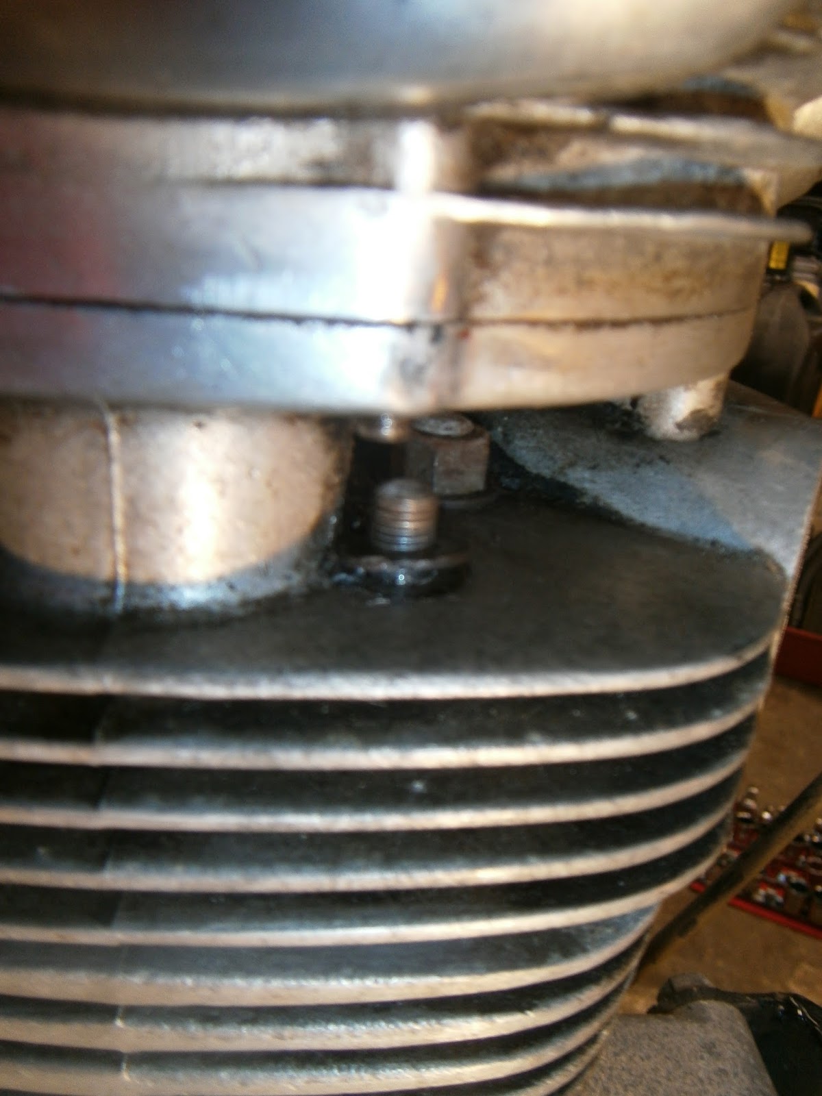
The studs are threaded into this flange and all the forces of valve opening against the springs must be resolved through the flange. Of course this is alloy and the studs are steel so over-tightening or even stress in service could strip the threads. During the 50 odd years that this bike has been in service and for whatever reason, this has happened here and the threads had stripped in some of the stud holes. The LH stud has stripped and been replaced with a through bolt and external nut/washer, RH stud is still threaded into the flange. This was presumably keeping the rocker box down but lacking internal threads, oil can bubble out from under this nut as the motor warmed.
 |
| LHS of cylinder head |
On the left the situation was even worse; The flange had cracked away exposing the threaded interior. Again the stud had been replaced with a through bolt and external nut. The repair is even less satisfactory here because the section of flange has come right away (and been lost), and the nut is therefore supported on one side only. This is tending to bend the bolt and pulling it forward and out of the recess into which it is now sitting. As I don't have the flange its not possible to TIG weld it back on.
Repairs can take different courses: The stripped thread hole could be repaired by helicoil (if not overly enlarged): If it is already too big for a helicoil then it could be drilled out to a known size and then tapped to a bigger thread. This will mean that I have to make up a two-diameter stud "special", thicker at the base than the top. Finally, the hole could be completely in-filled with weld or AL400 aluminium repair brazing rod. This is the harder rod with a 400 deg C melting temp and recommended for stressed areas like threads. The hole can then be re-drilled and tapped to the original size. The advantages of the last approach is that it keeps the standard stud sizes and that I could (in theory at least) do this myself (I cant TIG weld and lack the equipment).
The LHS is more problematic. If I had the missing piece I could have it welded back on, but as I don't, its a case of either making up a suitable new alloy lug and welding this back on, or attempting to rebuild the lug with weld or AL400 (no idea if this is possible). Followed of course by re-drilling and tapping. In any event, I don't think that such a repair is a DIY job.
Consequently I need to assess the costs of getting a used replacement head, which I anticipate would probably need reconditioning (with new guides at least), or paying for the repair (if it is actually possible) to my own head which appears to be in good condition already. NOTE I did in fact find a used head on fleabay for 30 quid! Two threads were stripped but the flange was intact (guides were both shot) so I will attempt to fix both.
Taking the head off
A relatively simple job to remove... I started by taking a few general shots for reference
 |
| RHS |
 |
| LHS |
 |
| LHS |
 |
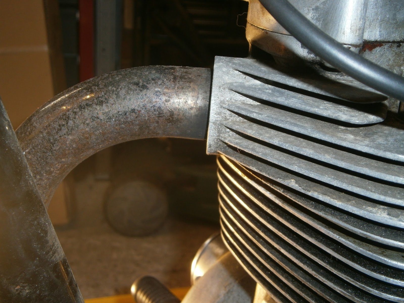
| Exhaust entry |
 |
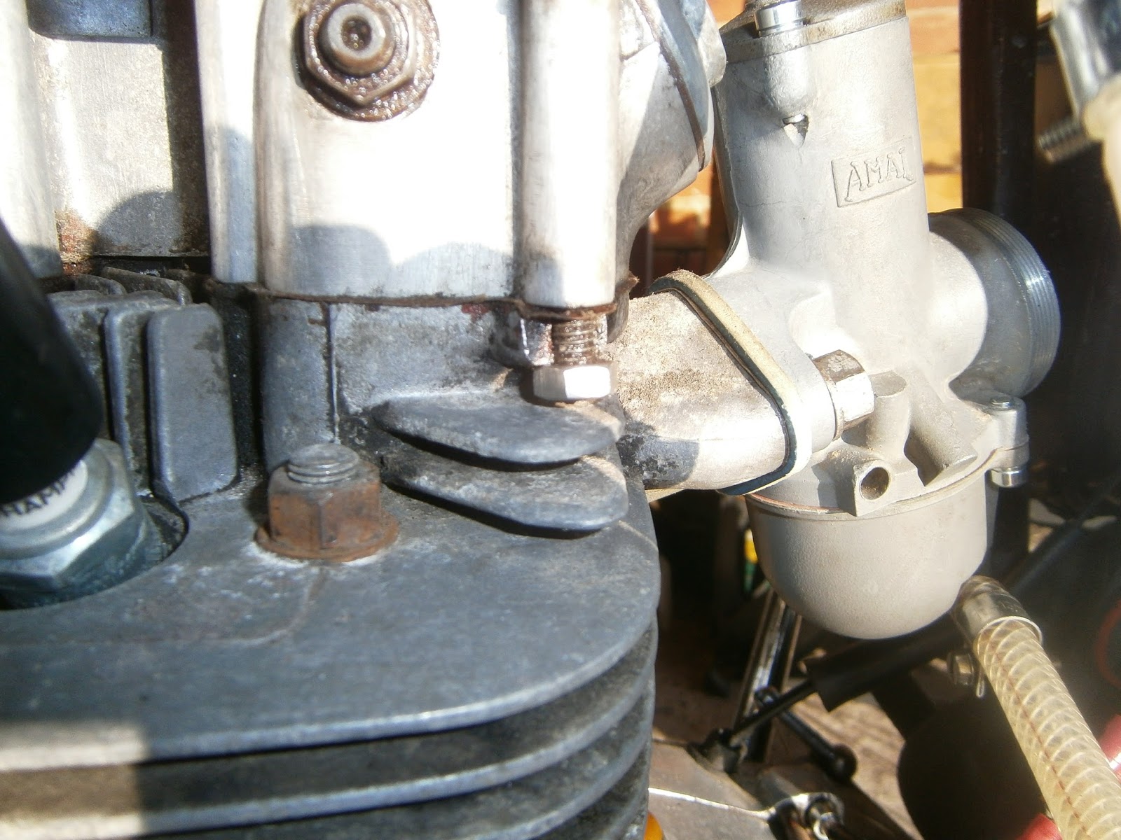
| Carb and rocker oil feed- on this bike the oil feed is into the case not via the rocker cap. |
 |
| Remove tank |
 |
| Disconnect oil feed pipe at pipe union |
 |
| Remove carb |
 |
| Tie carb up out of the way, flip oil feed pipe up there with it to stop drips. |
 |
| When I got the bike the PO referred to an oil leak- its never leaked in my hands, but I did find quite a lot of oil over the exhaust and framework on the RHS. I tracked this down to a leak at the bottom of the tank. I will see about fixing this when I reassemble. |
 |
| Silencer is bashed where the kickstart hits it- did all BSAs have this dent? BSA owners forum says that this damage occurs when the kickstart gets bent if the bike has been dropped. The solution is to re-bend the kick-start lever so that it runs clear of the silencer- I'm not absolutely convinced that this is the explanation as my lever doesn't look bent but maybe the damaged one was repaired or swapped? Oil contamination visible above silencer... |
 |
| ... and below oil tank |
 |
| Footrest needs to be released to remove the exhaust; When I looked at this I found a surprisingly large amount of play- this was laster found to be due to a dirty taper . |
 |
| Loosen the 5/16 nut on the inside and it will drop down out of the way. |
 |
| You cant pull the exhaust off (despite what the manual says) unless you remove this nut and the silencer. |
 |
| Note order: spacer, ex bracket, spring washer, nut |
 |
| Silencer is held onto a bracket with two nuts at the silencer side- difficult to access... |
 |
| ... and 2 bolts on the frame side- much easier so undo the 5/16 bolt here and the nut on the rear of the passenger's footrest |
 |
| With silencer released exhaust is a simple push fit in the head... I don't understand how this sort of fixing can ever seal! |
 |
| Head stay on top of head- it has a fastening for a decompression cable- which in my experience would be very useful! However no such cable is (or has ever been) present in the head |
 |
| So undo the stay |
 |
| noting the order of washers, Bolt-bracket, stay rod, plain washer and spring washer (parts manual shows a star lockwasher) and nut |
 |
| Once the stay is disconnected it can be swung up out of the way, I refit the nuts for storage |
 |
| Undo the two 5/8 AF nuts on the LHS |
 |
| ... and the 2 smaller WW nuts accessible on the right |
 |
| Here WW nut removed, note the remaining 2 larger AF nuts recessed below rocker box. These need to be undone which can just about be done- no idea how these could ever be re-torqued accurately though; perhaps an AF crowfoot spanner would work on a torque wrench? |
 |
| I removed the steady stay at this stage- probably could do this later but I wanted to make sure there was enough room to get the head out. |
 |
| Only 1 spring washer present- will need to find another- parts manual shows star washers here |
 |
| For some reason 2 flat washers between each side of the stay and head. Maybe needed as spacers or maybe should be above the stay? Need to check. if this is right.- Parts manual doesn't show this as the steady is split between head and frame illustrations. It appears that there should be two star lockwashers above the head steady and 1 on the brace stay. However spacers below the head stay are not illustrated- two washers do the job though so I'll stick with these. |
 |
| On this bike the horn has already been re-sited and so isn't in the way, the coil however should be removed for room- so make a note of the wore connections before slipping it out of the clamp and tieing it up on the frame tube |
 |
| The head then lifts off easily, note pushrods exposed, that it the front is the inlet |
 |
| Inlet pushrod front and angling towards rear of bike (left); ex pushrod angles to right. I tied a piece of tape around the inlet pushrod to ensure I didn't swap them. |
The head can then be rotated around the pushrods and lifted off revealing the piston beneath
 |
 |
| There seemed to be a bit more oil around the piston than expected but this could have come from the process of head removal. Piston is oversize as expected, not very badly carboned. Bores looked great with no ridge and nicely cross hatched from the honing. No scores or scratches. |
|
 |
| Head on bench, remove the remaining rocker box studs- and the offending bodge-bolt with lower nut. |
 |
| Stud pattern visible 2 x 5/16 3"studs at the front of the horseshoe (40-0127), a triangle of 3 x 3.25" longer studs (70-7996 behind ie on rhs of bike). Two short 1/4 inch studs (2 7/16" 40-939) are fitted at the front and two slightly longer 2 11/16" 1/4 inch studs (40-942) behind them on the side. The 5/16 studs need to be checked as they may have different threads at each end; coarse to enter the head and fine for the nuts, it wouldn't do to try and insert them the wrong way round! Later studs had the same thread on both ends, I also suspect that the subtle difference in 1/4 stud length was probably abandoned in later models. Note domed captive nuts and washers on all studs except the two above the inspection cover. I will need a few new studs and nuts to reassemble if I can get the threads repaired OK. |
 |
| Remove all nuts and rocker box containing the rockers comes off easily |
 |
| Damage to stud hole |
 |
| Exhaust side- how the head flange should look. |
I removed the valves using a valve compressor- BUT a word of warning. Make sure that when you use the compressor you position it so that the arm has a clear run over the rocker box mounting flange and touches only at the top of the valve. Any other route means that the compressor arm will foul on the rocker box mounting flange and its then simply trying to bend the rocker flange downwards- which will ruin any sealing when you reassemble! Its quite tricky to get the compressor into the right place as this job really needs about 4 hands- but it can be done.
 |
| Valves removed with a std compressor, keep all springs together with the valves and the right way up. |
I was shocked to find that the valves and guides were nowhere near as good as I had expected. They sealed very nicely but there was a lot of play in the guides and the valve stems were scratched and marked,. I hadn't expected to have to change them but it looks like I will need to.
 |
| Valve stem badly scored |
 |
| I could even feel a ridge just below the unworn part of the stem- measuring showed that the vale stem was 1.5 thou thicker in the unworn part! Its likely that the worst of the wear is in the stems but it does make sense to change the guides too- just to be safe. |
The inside of the head was more carboned than I expected- as were the valve heads, so its possible that oil has been entering down the guides after all. I removed the studs using stud extracting sockets... these aren't supposed to damage the threads but in fact they did and all needed to be restored with a die. Possibly this is because I have the cheap Bergen extractors, possibly Sealey or Laser would be better?
Removing the guides.
The guide installation tool consists of a stepped punch to fit 5/16 valve guides (ID) and the installation tools. To remove the guides first scrape as much carbon off their heads as possible since this will cause them to snag in their mounting holes in the head. The head is heated by boiling (or in the oven) and then locally with a butane torch. Support the head upside down on a piece of timber. The punch can then be inserted into the spark side of the guide and the guide punched out towards the spring side. This needed a heavy hammer but both came out easily enough. I checked them for size and continued -see my next blog!